Ford Fiesta wiring diagram: where electric energy "escapes"?


wiring diagramFrom time of the debut in 1976 car Ford Fiesta concerns the most favourite compact cars of Europe: after almost quarter of century its popularity remained invariable. It is exhausted already over ten millions cars Fiesta. Small Ford in all situations of a life is the reliable fellow traveller. By the way, once it was the first European car calculated on a method of a final element - FINITE-ELEMENT.An extent of all automobile life it constantly adapted to actual technical standards. Its basic concept has freely gone through all other concepts of a body: in company Ford car Fiesta is, as before, a synonym of a compact sedan with two or four doors, the various interior, established cross-section four-cylinder engines, a forward control and the big boot lid. But also version Fiesta of 96th series with new engines Zetec, the advanced chassis and considerably increased package of equipment has taken the higher places in ratings.
Short major keywords for Fiesta 96th series: anew developed 1,25-litre engine from light metals (55 kw / of 75 h.p.), the 1,8-litre diesel engine with the vortical chamber and the distributive fuel pump, four variants of the equipment, the increased active and passive safety, more perfect wiring diagram, an extensive package of comfort in all variants.
Till 1999 compact car Ford was delivered as Fiesta Foсus, Fiesta Flair, Fiesta Fun and Fiesta Ghia with three or five doors. "Practical" addition of car Fiesta belonged and belongs to car Courier name. The cabin small "auto truck" does not differ from all cars Fiesta, also from a technical aspect he offers the sedan standard.


wiring diagramWiring diagram of contact sockets and wiring harnesses in the car.
A- a contact socket; 1 - a wiring harness of the fan of a system cooling; 2 - a wiring harness of a motor compartment; 3 - an air conditioner wiring harness; 4 - an engine management system wiring harness; 5 - an ignition coil wiring harness; 6 - a wiring harness of a cleaner/washer of headlights; 7 - a radio receiver wiring harness; 8 - a wiring harness from a door to a door; 9 - a wiring harness of resetting of mirrors; 10 - a door wiring harness; 11 - a wiring harness of a pillow of safety; 12 - a wiring harness rear dynamics; 13 - a luggage compartment wiring harness; 14 - a boot lid wiring harness; 15 - a wiring harness of a fuel tank; 16 - a wiring harness of illumination of a selector lever of an automatic gear box; 17 - a wiring harness of illumination of interior; 18 - a wiring harness automatic podemno-sdvizhnogo the roof hatch; 19 - the main wiring harness; 20 - a windshield defroster wiring harness; 21 - the central electric block (CJB); 22 - a wiring harness of the switch of the compressor of the air conditioner; 23 - the distributive block (BJB); 24 - a wiring harness of the switch of light of a backing


However, wiring diagram Ford Fiesta has a number of "surprises".When still working the day before the accumulator battery suddenly do not develop current flow, more often it means, that the "secret" consumer in an onboard electrical network has completely discharged the battery. At first be convinced of it, having checked up wiring diagram and pressure on plugs of the accumulator battery. If necessary isolate the "secret" consumer.
SEQUENCE OF WORKS
1. For electrical leak definition, it agree wiring diagram unhook a wire from a negative side of the accumulator battery and connect the ampermeter between the plug of the accumulator battery and the unhooked wire. If at all disconnected consumers the ampermeter shows a current, means, you have a "secret" consumer of electric energy.
2. By turns check up all elements of wiring diagram. Connect a wire to a negative side of the accumulator battery, open a cover of the block of fuse plugs, serially take out safety locks and instead of a safety lock connect ampermeter probes. If the current is absent, the checked wiring diagram is serviceable. Even an insignificant current - not an occasion to anxiety. Such devices as an on-board computer, hours, a radio receiver and an intrusion protection constantly are energised the accumulator battery. But they spends much less electric energy, than at the faulty electric device.
3. Repeat measurements in the block of safety locks until your probing device will not show consumption of the big current. Under the table of safety locks it is necessary to define, what consumers of the electric power are connected to this electric circuit. Do not forget to check on wiring diagram.
4. By turns disconnect all electric devices of this chain and each time measure a consumed current. If the multiple-purpose probing device any more does not show consumption of the big current, means, you have found the "secret" consumer of the electric power.
READ MORE - Ford Fiesta wiring diagram: where electric energy "escapes"?

Car wiring diagram and the basic failures of starter Ford Escort 1980-1990.


car wiring diagramThe basic failures and methods of their elimination
1. At inclusion of starter the starter electric motor does not work
1.1. Failure of starter either the traction relay or defect in wires To check up being verified on car wiring diagram pressure presence on the plug 50 traction relays:
- Absence of pressure at starter inclusion testifies to damage wiring diagram an electric circuit
- Pressure presence testifies to failure of the traction relay or a starter
- If at inclusion of a starter pressure moves on the traction relay, but it does not work (there is no characteristic click), means, the traction relay (breakage of a winding or its short circuit on weight) is faulty
- Presence of characteristic click operation the traction relay testifies about scorching relay contacts or to failure of the starter
1.2. The electric motor is faulty
To check up work of the electric motor of a starter as short-term giving of pressure (an additional jump lead) on contact piece of the traction relay from the electric motor, being verified on wiring diagram. If the electric motor starts to work, means, it is necessary to search for a cause of defect in the traction relay


car wiring diagram


Fig.1. Ford Escort car wring diagram: Ford Escort starter Bosch. 1 - head; 2 - drive gear knot; 3 - drive gear lever; 4 - electromagnetic switch; 5 - stator; 6 - rotor; 7 - brush-holder


car wiring diagram


Fig.2. Car wiring diagram: Ford Escort starter Lucas. 1 - head; 2 - drive gear knot; 3 - drive gear lever; 4 - electromagnetic switch; 5 - stator; 6 - rotor; 7 - blank-end cover with a brush-holder


carwiring diagram


Fig.3.Car w iring diagram: Ford Escort starter Nippondenso 1 - head; 2 - drive gear knot; 3 - drive gear lever; 4 - electromagnetic switch; 5 - stator; 6 - rotor; 7 - brush-holder


2. The starter rotates slowly and does not start the engine
2.1. The accumulator is discharged
- To charge the accumulator
2.2. In an engine lubricating system too dense oil is filled in
- To replace oil
2.3. Graphite brushes are insufficiently pressed to a collector of the electric motor of a starter
- To adjust distance between graphite brushes and a collector
2.4. A bad condition of a work face of a collector starter bearings also are worn out
- To check up and, if necessary, to replace worn-out parts

3. At releasing the ignition key from position "starting engine operation" the starter continues to work
3.1. Sticking contact pieces of the traction relay
3.2. The ignition lock does not disconnect a starting circuit
- Immediately to switch off ignition and to disconnect the accumulator, then to eliminate failure.
READ MORE - Car wiring diagram and the basic failures of starter Ford Escort 1980-1990.

Engine HONDA CIVIC Removal


1. Open a cowl how much it probably.
2. Unhook at first a negative side of the accumulator battery, then positive.
3. Remove a mantle of racks (engines V16A2, В16А4, В16А5, В16А6).
honda spare parts
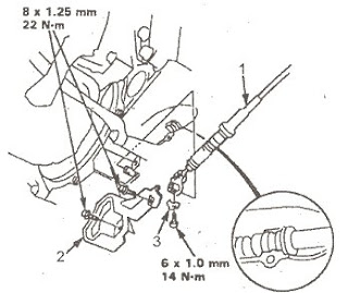
4. Unhook cables for connection from the block of safety locks and the relay.
honda spare parts5. Remove the accumulator battery and a bracket of fastening of the accumulator battery.
honda spare parts6. Remove an inlet air vent and the air filter case.
Engines D14A3, D14A4, D15Z4, D15Z5, D16Y7:
1. Remove the resonator and an inlet air vent.
honda spare parts2. Unhook a socket of a temperature detector of air on an admission, then remove the air filter case.
honda spare partsExcept engines D14A3, D14A4, D15Z4, D15Z5, D16Y7:
1. Unhook a socket of a temperature detector of air on an admission, then remove an inlet air vent and the air filter case.

honda spare parts1 - the air filter case; 2 - an inlet air vent; 3 socket of a temperature detector of air on an admission.
7. Unhook a socket of a wiring harness of the engine.
honda spare parts1 - a socket of a wiring harness of the engine
8. Dump pressure of fuel, to slacken a technological bolt on a fuel filter approximately one turn.
Do not smoke at work on a fuel system. Hold an open flame far from work area. Merge fuel in suitable capacity.
9. Remove a hose of system of removal of steams of fuel from the inlet pipe duct and a fuel hose.
Engines D14A3, D14A4, D15Z4, D15Z5, D16Y7:
honda spare parts1 - a hose of system of removal of steams of fuel from the inlet pipe duct; 2 - a bolt;
3 - a technological bolt; 4 - hollow disks; 5 - a hollow disk; 6 - a fuel hose.
Except engines D14A3, D14A4, D15Z4, DD15Z5, D16Y7:
honda spare parts1 - a technological bolt; 2 - a bolt; 3-hollow disks; 4 - a hollow disk; 5 - a fuel hose;
6-hose of system of removal of steams of fuel from the inlet pipe duct.
10. Remove a vacuum hose of the vacuum servo of brakes, a hose of return of fuel and a vacuum hose.
Engines D14A3, D14A4, D15Z4, D15Z5, D16Y7:
honda spare parts1 - a vacuum hose; 2 - a vacuum hose of the vacuum servo of brakes; 3 - a hose of return of fuel.
Except engines D14A3, D14A4, D15Z4, D15Z5, D16Y7:

honda spare parts1 - a vacuum hose; 2 - a hose of return of fuel; a 3-vacuum hose of the vacuum servo of brakes.
11. Unhook sockets ESM/RSM.
12. Unhook the basic socket of a wiring harness.
13. Remove isolating boot and wiring harness clamps, then remove sockets ESM/RSM.
honda spare parts1 - an isolating boot.
14. Remove a belt of a drive gear of the pump of the hydraulic booster of a steering and the pump.
ATTENTION: do not unhook hoses from the hydraulic booster pump.
Engines V16A2. В16А4, В16А5. В16А6:
1. Remove an adjusting bolt and fastening bolts, then remove a belt of a drive gear of the pump of the hydraulic booster and the pump. Engines V16A2, В16А4, В16А5, В16А6:
honda spare parts1 - an adjusting bolt; 2 - fastening bolts.
Except engines V16A2, В16А4, В16А5, В16А6:
1. Remove a bolt of fastening and fixing bolt, then remove a belt of a drive gear of the pump of the hydraulic booster and the pump.
Except engines V16A2. В16А4. В16А5, В16А6:
honda spare parts1 - a fastening bolt;
2 - a belt of a drive gear of the pump of the hydraulic booster;
3 - a fixing bolt.
15. Remove a belt of a drive gear of the compressor of the air conditioner. Engines V16A2. В16А4. В16А5. В16А6:
1. To slacken a bolt of a bracket of a roller and an adjusting bolt, then remove a belt at water of the compressor of the air conditioner. Engines V16A2. В16А4. В16А5, В16А6:
honda spare parts1 - an adjusting bolt;
2 - a bolt of a bracket of a roller;
3 - a belt of a drive gear of the compressor of the air conditioner.
Except engines V16A2, В16А4, В16А5, В16А6:
1. To slacken the central nut of a roller and an adjusting bolt, then remove a belt of a drive gear of the compressor of the air conditioner. Except engines V16A2. В16А4. В16А5, В16А6:
honda spare parts1 - an adjusting bolt;
2 - the central nut of a roller;
3 - a belt of a drive gear of the compressor of the air conditioner.
16. Remove a cable of a drive gear of a throttle valve, to slacken a lock nut, then take the end of a cable from sector.
ATTENTION: Do not bend a cable at removal of it. Always replace the damaged cable new. Adjust a cable of a drive gear of a throttle valve at assembly. Engines D14A3, D14A4, D15Z4, D15Z5, D16Y7:
honda spare parts1 - a lock nut;
2 - an adjusting nut;
3 - a cable of a drive gear of a throttle valve.
Except engines D14A3, D14A4, D15Z4, D15Z5, D16Y7:

honda spare parts1 - a cable of a drive gear of a throttle valve;
2 - a lock nut;
3 - an adjusting nut.
17. Remove a clutch working cylinder in gathering with a tube and a hose (a mechanical check point).
ATTENTION: Do not unhook a tube. Do not press a clutch pedal, at a remote working cylinder. Do not bend a tube.
honda spare parts1 - a working cylinder
18. Remove an earth wire of a gear box and a hose loose strap.
honda spare parts1 - a hose loose strap; 2 - a gear box earth wire.
19. Remove a steering cable (CVT/HONDA MULTI MATIC).
honda spare parts1 - a splint; 2 - a hollow disk; 3 - a lock nut; 4 - a plastic hollow disk; 5-cable of steering.
20. Unhook a socket of the gauge of change of effort on a steering wheel depending on speed of movement, and remove a wiring harness clamp.
honda spare parts1 - a socket of the gauge of change of effort on a steering wheel depending on speed of movement.
21. Remove a radiator cover. At removal of a cover of a radiator wait before drop of temperature of a cooling fluid to avoid a burn.
22. To hoist the hoist on full height.
23. Remove front wheels and crankcase protection.
honda spare parts1 - crankcase protection.
24. Merge a cooling fluid.
25. Merge a transmission oil or a liquid. Repeatedly establish a drain plug, using a new hollow disk.
26. Merge engine oil. Repeatedly establish a drain bolt, using a new hollow disk.
27. Remove a shift rod and a longitudinal rod (a mechanical check point).
honda spare parts1 - a shift rod; 2 - a clamper; 3 - a rod; 4 - a spring pin of 8 mm.
28. Remove a steering cable (Models from an automatic check point).
ATTENTION: Do not bend a cable. Always replace the damaged cable new. Adjust a cable at assembly.
honda spare parts1 - a steering cable; 2 - a cover of a cable of steering; 3-lock washer.
29. Remove the air conditioner compressor.
ATTENTION: do not unhook hoses of the compressor of the air conditioner.
honda spare parts
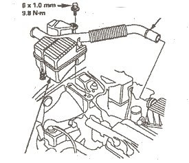
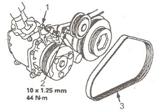
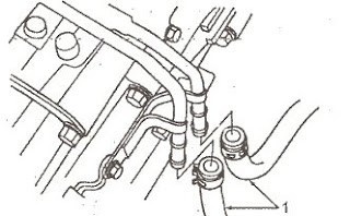
1 - the air conditioner Compressor
30. (Engines V16A2, В16А4, В16А5) Unhook a socket of the warmed up oxygen gauge.
31. Remove an exhaust pipe And.
honda spare partsExcept engine D15Z5, D15Z6, D15Y5 (models КЕ, KG), D16Y7
honda spare parts1 - a socket of the warmed up oxygen gauge;
2-layer pads; 3 - a layer pad; 4 - a nut;
5 exhaust pipe And; 6 - a nut.
32. Remove the right plug of the absorber.
33. Unhook spherical hinges of a lower arm of a suspender.
34. Remove power shafts.
35. Lower the hoist.
36. Remove the top and bottom radiator hoses, and also a heater hose.
honda spare parts1 - the top radiator hose; 2 - a heater hose;
3-hose of a heater; 4 - the bottom radiator hose.
37. Remove hoses of a cooler of a working liquid of an automatic gear box, then blank off hoses a tube (models from an automatic check point. CVT/HONDA MULTI MATIC).
honda spare parts1 - hoses of a cooler of a working liquid of an automatic gear box
38. Connect winch fastening to hooks of lifting of the engine.
Engines D15Z5, D15Z6, D16Y5 (models КЕ, KG), D16Y7:
1 - layer pads; 2 - a nut;
3 - an exhaust pipe And; 4 - a nut.
honda spare parts
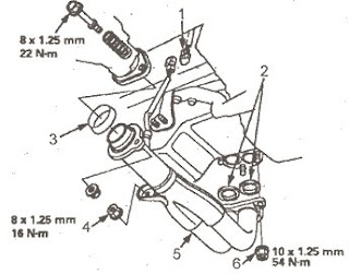
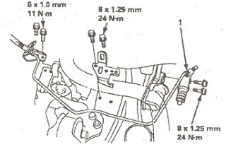
39. Remove the left and right front bearing parts of fastening.
honda spare parts1-left front bearing part; 2 - a nut.
honda spare parts1 - the right front bearing part; 2 - a bolt.
40. Remove a rear bearing part.
honda spare parts1 - a bolt; 2 - a rear bearing part; 3 - bolts.
41. Remove the top bracket.
honda spare parts1 - the top bracket.
42. Remove a bracket of fastening of a gear box, then remove a gear box bearing part.
honda spare parts1 - a gear box bearing part; 2 - a bracket of fastening of a gear box.
43. Check up, that before removal of the engine you have unhooked all hoses and sockets which can prevent removal.
44. Slowly hoist the engine approximately 150 mm. Check up once again. That all hoses and wires have been unhooked from the engine/gear box.
45. Completely hoist the engine, and remove it from the car.
READ MORE - Engine HONDA CIVIC Removal

Honda Civic Parts | Engines (DOHC)


Honda Civic engines with two camshafts (DOHC):
An arrangement of components:

Honda Civic Parts - engines B16A2, B16A4, B16A5, B16A6
honda civic parts1. Air temperature detector on an admission
2. The gauge of position of a throttle valve
3. The gauge of an absolute air pressure
4. The valve of steering of idle running
5. The electromagnetic valve of system of removal of steams of fuel (engine B16A2 of model KG, KE, KQ, KM)
6. The gauge of electric loading (model KU)
7. The gauge of steering of the booster of a steering (model KU)
8. Gauge VMT of position of a knee shaft and cylinder number
9. The detonation gauge (KS)
10. A car speed sensor
11. A cooling fluid temperature detector
12. The warmed oxygen gauge (for models with neutralizer)
13. A three-componental catalyst converter

Honda Civic Parts - engines D15Z6, D15Z7, D16Y5, D16Y6, D16Y8
honda civic parts1. The gauge of lifting of the valve of system of recirculation (except engines D16Y5 (model KQ), D16Y6, D16Y8)
2. The gauge of position of a throttle valve
3. The gauge of an absolute air pressure
4. The valve of steering of idle running (manual transmission)
5. The electromagnetic valve of steering of recirculation of combustion materials (except engines 16Y5 (model KQ), D16Y6, D16Y8)
6. Air temperature detector on an admission
7. The electromagnetic valve of system of removal of steams of fuel (engine D15Z6)
8. The gauge of electric loading (model KG, KE, KU, KQ)
9. The pressure control device of the booster of a steering (model KG, KE, KU, KQ)
10. A car speed sensor
11. The detonation gauge (D15Z7, D16Y5, D16Y6, D16Y8)
12. The electromagnetic valve of steering of blocking (models with automatic transmission) (engines D15Z6, D16Y5 (model KQ), D16Y6)
13. The gauge of fluctuation of a rotary speed of a knee shaft
14. A cooling fluid temperature detector
15. The valve of steering of idle running (models with automatic transmission)
16. A three-componental catalyst converter (engine D15Z7 and D16Y5 (model KQ), D16Y8)
17. The oxygen gauge (engine D15Z7, D16Y5 model KQ); the warmed up oxygen gauge (engine D16Y8)
18. A three-componental catalyst converter (engine D15Z6 and D16Y5 (models KG, KE))
19. The oxygen gauge (engine D15Z6); the warmed up oxygen gauge (engine D16Y5 of model KG, KE)

Honda Civic Parts - engines D16Y7
honda civic parts1. The gauge of electric loading (model KH)
2. A car speed sensor
3. The gauge of position of a throttle valve
4. The gauge of an absolute air pressure
5. Air temperature detector on an admission
6. The pressure control device of the booster of a steering (model KH)
7. Gauge VMT of position of a knee shaft and cylinder number
8. A cooling fluid temperature detector
9. The electromagnetic valve of system of removal of steams of fuel
10. A three-componental catalyst converter
11. The oxygen gauge
12. The valve of steering of idle running

Honda Civic Parts - engines B16A2, B16A4, B16A5, B16A6
honda civic parts1. An air filter
2. The throttle valve case
3. A cable of a drive gear of a throttle valve
4. The resonator
5. The valve of the raised rotary speed of idle running at warming up
6. The valve of system of ventilation of a crankcase

Honda Civic Parts - engines D15Z6, D15Z7, D16Y5, D16Y6, D16Y8
honda civic parts1. An air filter
2. The throttle valve case
3. A cable of a drive gear of a throttle valve
4. The resonator
5. The valve of system of ventilation of a crankcase

Honda Civic Parts - engines D16Y7
honda civic parts1. An air filter
2. A cable of a drive gear of a throttle valve
3. The resonator
4. The valve of system of ventilation of a crankcase
5. The throttle valve case

Honda Civic Parts
honda civic parts1. A spray jet
2. The snubber of a pulsation of pressure of fuel
3. The accumulator of steams of fuel
4. A fuel filter
5. A fuel bringing tube
6. A tube of removal of steams of fuel
7. The fuel indicator block
8. A fuel pump
9. A cover of a fuel mouth
10. A fuel tank
11. The valve of the accumulator of steams of fuel
12. A fuel tube / joint
13. A tube of return of fuel
14. A fuel pressure regulator

Honda Civic Parts
honda civic parts1. A mixture control assembly idling (models without a catalyst converter)
2. The inertial switch (models KG, KE, KS)
3. The main relay of system of injection
4. A diagnostic socket
5. An electromagnetic control package the engine
READ MORE - Honda Civic Parts | Engines (DOHC)
 
Copyright Car Wiring Diagrams All Rights Reserved
Powered by Home Recordings
ProSense theme created by Dosh Dosh and The Wrong Advices.
Blogerized by ExTemplates.com Blogger Templates.