Ford Mustang EFI Nitrous Oxide System Car Wiring Diagram.


---------------------------------------------------------------------------------------------------
car wiring diagramNitrous is the most cost effective way to increase the performance of an internal combustion engine. The way wiring diagramit works is to increase the amount of oxygen that can be introduced into the cylinder during the intake stroke. With more oxygen, more fuel can be burned, and thus, the engine produces more power. This equation works without exception as long as the proper amount of fuel is added to the cylinder to match the nitrous charge. If the fuel is not added, the engine is forced into a lean condition which causes combustion temperatures to increase, along with the potential for massive engine failure. Following article discusses about the Electronic Fuel Injection Nitrous Oxide System Car Wiring Diagram for Ford Mustang. The nitrous system consists of four main components: nitrous system of delivery, fuel delivery system, system plate, and electric system.


cfr wiring diagram


Fig.1. Ford Mustang EFI Nitrous Oxide System Car Wiring Diagram.


Appropriate and safe wiring of nitrous system also is important for consecutive performance data. Nitrous Works are recommended strongly by use of electric relays, thus a drawn game of force of a current from solenoid coils does not damage switches of activation and to assure appropriate solenoidal function.
READ MORE - Ford Mustang EFI Nitrous Oxide System Car Wiring Diagram.

2002 Nissan Frontier Car Wiring Diagram Electrical System Troubleshooting.


car wiring diagramNissan Frontier - the name for D22 and D40 generations of pickups of Nissan entered in 1998, also was replacement for ageing 1986 Nissan Hardbody Truck. The boundary car wiring diagram Nissan the following wiring diagram and electric search of failures of system asks 2002 series Nissan Frontier.
The electric system covers discussion on Supplemental Restraint System (SRS), air bag, set belt pre-tensioner wiring diagrams and trouble diagnosis, harness connector, standardized relay, power supply routing, ground distribution system,


car wiring diagram


Fig.1. Nissan Frontier car wiring diagram.


combination switch check and replacement, steering switch check, headlamp, parking/license/tail lamps, stop lamps, back-up lamps, front fog lamps, turn signal and hazard warning lamps, illumination, interior room lamp,
meters and gauges, compass and thermometer, wiper and washer, audio system schematic/wiring diagram troubled diagnosis and inspection, audio antenna, door mirror, automatic speed control device, power window, power door lock, remote keyless entry system, smart entrance control, electrical unit locations, harness layout, bulb specifications, and car wiring diagram codes.
READ MORE - 2002 Nissan Frontier Car Wiring Diagram Electrical System Troubleshooting.

Jeep Grand Cherokee: wiring diagram of a starting engine operation from the auxiliary power supply.


wiring diagram
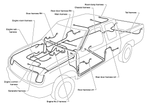
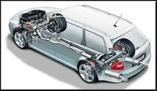
Jeep Grand Cherokee (1993-1999 ) is calculated on strong by spirit, the strong people tempered on travel. It leaves nobody indifferent. He equally confidently feels on wood roads and lines with firm coverings. Ease in the steering, the interior thought over to trifles, smoothness of a course should cause admiration as the driver, and passengers. It is the car for those who appreciates the present force, true friendship and command spirit - with it on a shoulder overcoming of any obstacles and obstacle.Jeep Grand Cherokee - present Not for road car combining the best technical achievements of Europe and traditional American design. Engineers DaimlerChrysler have created this masterpiece, making use of 60-year-old experience of creation of all-wheel drive cars.
Jeep wiring diagram engages 12 In system of an electrical equipment about grounding on a negative pole. A food of all lighting instruments and electric units is carried out from the battery of lead-acid type recharged from the alternator.
There comes the moment when there is a reason, that you Jeep is not started. You look wiring diagram- it an order. The reason - the discharged accumulator. It is necessary a starting engine operation from the auxiliary power supply. Also at performance of any works on repair and service of components of wiring diagram it is necessary to unhook preliminary without fail a negative lead from the battery (or to remove the battery) in order to avoid electrotrauma and-or ignition reception.
At a starting engine operation from the auxiliary battery it is necessary to remember necessity of performance of following requirements:

* Before connection of the auxiliary battery make sure, that ignition is switched off (a key will turn in position OFF).
* Make sure, that all electrical equipment of the car (lighting instruments, a heater, window wipers, etc.) is switched off.
* Necessarily put on goggles.
* Make sure, that the auxiliary battery on an output voltage corresponds established on your car.
* If start is made from the battery established on other car, track, that between cars there were no things in common!
* Make sure, transmission is established on neutral drive , or in position “Р” (Parking) .
* If the auxiliary battery concerns type subject to service, remove from it ventilating covers and cover bores with rags.
Assemble such wiring diagram.
Connect a red wire from the complete set for a starting engine operation from an auxiliary source between positive (+) plugs of both batteries. Then connect the second (black) wire from the complete set at first to negative (-) the plug of the auxiliary battery, and then to well earthed point on your car (such as a bolt or a bracket on the engine block, whenever possible within distance in 45 sm from the battery). Check up wiring diagram. Make sure, that wires do not touch moving components of an impellent compartment (such as fan baffles, drivebelts, etc.).


wiring diagram


Wiring diagram of a starting engine operation from the auxiliary power supply.

Starting engine operation from auxiliary power supply Jeep Grand Cherokee Connect wires from the complete set for start of the car from the auxiliary power supply as it should be shown on wiring diagram (Pay attention, that the negative lead of the auxiliary battery is not connected to a negative side of the sat down battery).


Start the engine from the auxiliary battery, then, having left its working on single turns, engage the motor of the fan of a heater (for the maximum speed) or a defroster of glass for smoothing of peaks of pressure which can arise at unhooking of wires (do not engage lighting instruments since considerable jumps of pressure can lead lamps to burn down). Unhook wires, operating as it should be the return to an order of their connection, in conformity with wiring diagram.
READ MORE - Jeep Grand Cherokee: wiring diagram of a starting engine operation from the auxiliary power supply.

Car Wiring Diagram: in flight on Dodge Challenger.


Car Wiring Diagram watches novelties auto industries. Here the Air Forces of the USA have decided to construct something absolutely unreal. The American military men have constructed on money of tax bearers two not that of the car, not that of fighter. As donors have acted Ford Mustang and Dodge Challenger. The first after the spent works has received name X-1, the second - Vapor.
First of all at both masl-karov have replaced standard details of body coal-plastic, having given to appearance much more aggression. To change have undergone wiring diagrams. Lamps of head light at cars blink now, as if landing fires of planes, and the input in interior occurs through guillotine-type doors. But completely to estimate alteration, it is necessary to glance inside. The interior of the Mustang is so well stylised under a fighter cockpit, that it not at once recognise as automobile. The driver sits in the middle in plane armchair, instead of a wheel before it joystick, the plane metre panel with mad quantity of toggle-switches is established.

Is hardly quieter under the certificate of correspondent Car Wiring Diagram, in Vapor which is stylised under the plane-invisible being the Stealth. Instead of habitual pedal of an accelerator - the aviation hand lever of giving of pull-rod, and steering wheels, is more true than steering wheels, here whole two. The quite good car for driving school at the same time has turned out. But whether these samples that what to fly are capable, and at least more or less tolerably to go? We know only, that under Ford's X-1 cowl is 500-strong V8 4.6 with advanced system of cooling, and what interiors at Dodge, and at all is not informed. But in the Air Forces of the USA with pride underline, that both cars are completed with plane helmets.


car wiring diagram


Fig.1. Car Wiring Diagram represents Ford Mustang - X-1.


car wiring diagram


Fig.2. Car Wiring Diagram represents Dodge Challenger - Vapor.


car wiring diagram


Fig.3. Car Wiring Diagram : interior of the Dodge Challenger - Vapor is so well stylised under a fighter cockpit.
---------------------------------------------------------------------------------------------------
READ MORE - Car Wiring Diagram: in flight on Dodge Challenger.

Honda wiring diagram


Honda wiring diagram... Repair of an electrical equipment Honda is an uneasy problem which necessarily demands presence from you an Honda wiring diagram. As all cars and motorcycles Honda are difficult enough in the constructive plan and every year are still improved. And nevertheless to execute repair of an electrical equipment of the car or a motorcycle Honda in house garage and to save thus money it is possible. In general Honda makes very reliable cars and motorcycles. But, after several years of operation to repair an electric part of the car or a motorcycle Honda it is necessary. The durability of operation of this or that element of an electrical equipment directly depends on character of driving and leaving of the owner of the car or a motorcycle. For example, repair of starter Honda. The manufacturer recommends to check a starter on serviceability each 3-4 years, thus effective term of their operation does not exceed 7-10 years.
But, if to adhere to several service regulations, repair of an electrical equipment can and not be necessary for owners Honda. Or to do this repair it is necessary much later. In rainy weather which "pleases" us during the winter period, it is necessary to give a maximum of attention to cleanliness of the iron friend not only outwardly, but also from within. The dirt getting into all cracks and a moisture makes destructive impact on all electronic blocks of the car, therefore it is necessary to take measures on clarification and drying of whimsical details of the car.
If repair all the same is inevitable also you have decided to make it independently, I can recommend this Honda wiring diagram archiv in which it is possible to find assembly Honda wiring diagram practically for any cars and motorcycles Honda.

Honda wiring diagram (Civic)
Honda wiring diagram (Civic)Honda wiHonda wiring diagram (Accord)ring diagram (Accord)
Honda wiring diagram (Prelude)
READ MORE - Honda wiring diagram

Honda Civic Parts | Engines (SOHC)


Honda Civic parts, engines with one camshaft (SOHC):
An arrangement of components:

Honda Civic Parts - engines D14A3, D14A4, D15Z4, D15Z5:
honda civic parts1. A car speed sensor
2. The electromagnetic valve of system of removal of steams of fuel (engine D14A3, D14A4)
3. The gauge of position of a throttle valve
4. The gauge of an absolute air pressure
5. The gauge electric loadings (engine D15Z5)
6. Air temperature detector on an admission
7. Gauge VMT
8. The electromagnetic valve of steering of blocking (models with an automatic gear box)
9. The pressure control device of the booster of a steering (engine D15Z5)
10. A cooling fluid temperature detector
11. The valve of steering of idle running
12. The oxygen gauge (engine D14A3, D14A4)
13. A three-componental catalyst converter (engine D15Z5)
14. A three-componental catalyst converter (engine D14A3, D14A4)
15. The oxygen gauge (engine D15Z5)

Honda Civic Parts - engines D16Y4, D16Y9:
honda civic parts1. Gauge VMT (on the distributor)
2. Air temperature detector on an admission
3. The gauge of position of a throttle valve
4. The gauge of an absolute air pressure
5. The valve of steering of idle running
6. A car speed sensor
7. The electromagnetic valve of steering of blocking (models with an automatic gear box)
8. A cooling fluid temperature detector
9. The oxygen gauge (engine D16Y4)
10. A three-componental catalyst converter (engine D16Y4)

Honda Civic Parts - engines D14A3, D14A4, D15Z4, D15Z5:
honda civic parts1. An air filter
2. A cable of a drive gear of a throttle valve
3. The resonator
4. The valve of system of ventilation of a crankcase
5. The throttle valve case
READ MORE - Honda Civic Parts | Engines (SOHC)

Car wiring diagram : 2009 Chevrolet Silverado Instrument Panel Fuse Block and Relay.

car wiring diagramRepresented Car Wiring Diagram 2-Mode Hybrid, the new Chevrolet Silverado Hybrid boasts almost 50% better fuel efficiency over previous model years while maintain 100% of the muscle. Among one of its most impressive features; engaged in Mode 1, the Silverado Hybrid’s wiring diagram propulsion is capable of independently powering the vehicle at low speeds, even while towing at maximum capacity [6,100 lbs]. An new car wiring diagram Electronically Variable Transmission [EVT] is jointly powered by both a 6.0L V8 gasoline engine and 300-volt NiMH battery, boosting the Silverado Hybrid’s overall output to 332-hp. A 2-Mode vehicle-standard regenerative braking system provides a constant source of electric energy that helps the Silverado Hybrid’s 26-gallon fuel tank average a cruising range of over 500 miles.

car wiring diagram


Fig.1.Wiring diagramme Chevrolet silverado the fuseboard relay


Fuse plug function / the Protected Chain

1- Rear Seats

2 - Rear Accessory Power Outlet

3 - Steering Wheel Controls Backlight

4 - Driver Door Module

5 - Dome Lamps, Driver Side Turn Signal
6 - Driver Side Turn Signal, Stoplamp

7 - Instrument Panel Back Lighting

8 - Passenger Side Turn Signal, Stoplamp

9 - Passenger Door Module, Driver Unlock

10 - Power Door Lock 2 (Unlock Feature)

11 - Power Door Lock 2 (Lock Feature)

12 - Stoplamps, Center-High Mounted Stoplamp

13 - Rear Climate Controls

14 - Power Mirror

15 - Body Control Module (BCM)

16 - Accessory Power Outlets

17 - Interior Lamps

18 - Power Door Lock 1 (Unlock Feature)

19 - Rear Seat Entertainment

20 - Ultrasonic Rear Parking Assist, Power Liftgate

21 - Power Door Lock 1 (Lock Feature)

22 - Driver Information Center (DIC)

23 - Rear Wiper

24 - Cooled Seats

25 - Driver Seat Module, Remote Keyless Entry System

26 - Driver Power Door Lock (Unlock Feature)


Circuit breaker - Function / the Protected Chain
LTDR - Circuit breaker of the Power window of the Party of the Driver

Harness connector - Function / the Protected Chain

LTDR - Door Communication of the Harness of the Driver

The case - Harness connector
READ MORE - Car wiring diagram : 2009 Chevrolet Silverado Instrument Panel Fuse Block and Relay.

1997 FORD TAURUS WIRING DIAGRAMS


1997 Ford Taurus System Wiring Diagram

Complete wiring diagrams for 1997 Ford Taurus Vehicle. here you’ll find wiring schematic regarding; A/C Circuit, Auto A/C, Anti-lock Brake Circuits, Anti-theft Circuit, Body Computer Circuits, Computer Data Lines, Cooling Fan Circuit, Cruise Control Circuit, Defogger Circuit, Electronic Power Steering Circuit, Electronic Suspension Circuit, 3.0L 12-Valve, Engine Performance Circuits, 3.0L 24-Valve, Engine Performance Circuits, 3.0L Flex Fuel, Engine Performance Circuits, 3.4L SHO, Engine Performance Circuits, Back-up Lamps Circuit, Sedan, Back-up Lamps Circuit, Wagon, Exterior Lamps Circuit, Sedan W/ Lamp Out Warning, Lamp Outage Module Circuit, Ground Distribution Circuit, Autolamps Circuit, Headlamps Circuit, Headlamps Circuit, Horn Circuit, Instrument Cluster Circuit, Lamp Outage Circuit, Instrument Cluster Circuit, Courtesy Lamps Circuit, Instrument Illumination Circuit, Power Antenna Circuit, Power Distribution Circuit, Power Door Lock Circuit, Power & Lumbar Seat Circuit, Power Window Circuit, Shift Interlock Circuit, Charging Circuit, Supplemental Restraint Circuit, Trunk Release Circuit.
READ MORE - 1997 FORD TAURUS WIRING DIAGRAMS

Honda Muffler Parts - General Questions


The difficult design of exhaust system Honda is presented by several components. Perhaps, it is possible to name the basic part muffler Honda. In the USA market this detail is represented by known firms, whose production is delivered on the conveyor and five years' term of uninterrupted operation is guaranteed. In three-componental system of exhaust Honda the important place occupies flute Honda which attaches the muffler directly to a motor compartment. The important qualities гофры is its raised elasticity and ability to transfer the big temperature loadings. Flute Honda in the form of a three-layer texture it is capable to serve to your car not less than two years. Because of some reasons exhaust system components can break the functioning and demand repair of the muffler, replacement flute Honda. As the system of an exhaust of the given mark of the car includes catalysts Honda which trouble-free work directly depends on the natural reasons and use of poor-quality gasoline and oil. Thus there is an infringement and failure in work not only an exhaust system, but also all engine completely.

Honda muffler parts
honda muffler parts
Honda muffler parts
honda muffler partsHonda muffler parts
honda muffler parts
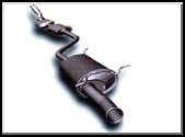
At a wish, in the course of repair of the muffler instead of a standard exhaust system it is possible to establish the direct-flow muffler that will give to the car a sports view and will provide power inflow.
READ MORE - Honda Muffler Parts - General Questions

FORD MUSTANG WIRING DIAGRAM INSTRUMENT CLUSTER


Ford Mustang Wiring Diagram for 1987-1993 Instrument Cluster

If you are attempting to install a 1990-1993 steering wheel in a 1987-1989 car, then the steering column must also be changed. All connections will hook up in the steering column except for the harness from the steering wheel, which provides the horn and cruise control signal. The windshield wipers will not work if the 1990-1993 switch is used on the 1987-1989 harness. Testing with a multimeter will show you the wires that Ford chose to move when the design of the switch changes. All controls have the same wiring except the windshield wipers. After the correct wires are determined, it is an easy task to remove the wires from the plug by pressing down on the tab on the front of the plug and sliding the wire out the back. Then, the wire can be inserted into the previously unused connection hole on the plug.

This process if much easier if you have an old harness from a 1990-1993 that comes out of the instrument cluster. The wires need to be as long as possible (6-8 inches), and they can be successfully wire tapped and soldered to the factory 1987-1989 harness.
READ MORE - FORD MUSTANG WIRING DIAGRAM INSTRUMENT CLUSTER

Car wiring diagram : 2007 Suzuki Reno Engine Compartment Fuse Box Relay and Circuit Breakers.

car wiring diagramCar Wiring Diagram studies electric equipment 2007 Suzuki Reno. For 2007 the Suzuki Forenza comes available in sedan or wagon bodystyle; in both automatic and manual transmissions. A 2.0-liter, 143-horsepower, four-cylinder engine powers all models. Standard equipment wiring diagram includes air conditioning with a micron air-filtration system, all power conveniences, heated exterior mirrors, and AM/FM stereo with CD and MP3. Safety features on all models include tire pressure monitor, and dual front and side impact airbags. An optional Convenience Package is available which includes keyless remote entry and cruise control. The Popular Package includes the Convenience Package items and adds a power tilt-and-slide sunroof. The 2007 Suzuki Reno car wiring diagram are protected from short circuits by a combination of fuses, circuit breakers and fusible thermal links in the wiring itself. The engine compartment fuse block / box is located on the driver’s side of the vehicle, near the battery. The following wiring diagram and tables shows each Reno fuse / relay location and its circuit protected.


car wiring diagram


Fig.1.Wiring Diagram Suzuki Reno engine compartment fuse box.


Fuse Circuit Protected/ Usage

HEAD LAMPS - Head Lamp
ECM - Engine Control Module
I/P FUSE - Instrument Panel Fuse
FUEL PUMP - Fuel Pump
A/C - Air Conditioning

HORN - Horn
HI BEAM - Head Lamp High-Beam
DRIVER’S PWR WNDW - Driver’s Power Window

STOP LAMPS - Stop Lamps

DR/LCK - Door Lock

MIR HTD - Heated Mirror

FRT FOG - Front Fog

ILLUM LT - License Plate Lamp, Parking Lamp Left

INJ - Injector
ENG SNSR - EVAP - Canister Purge Solenoid, HO2S, Cooling Fan Relay
LOW BEAM LT - Head Lamp Low-Beam Left
ILLUM RT - Illumination Circuit, Parking Lamp Right

LOW BEAM RT - Head Lamp Low-Beam Right

SPARE - Spare
SPARE - Spare
SPARE - Spare

BATT PWR - Battery Power
ABS - Antilock Brake System
HVAC BLWR - HVAC Blower

IGN 2 - Ignition 2

IGN 1 - Ignition 1
FUSE PLR - Fuse Puller

COOL FAN LOW - Cooling Fan Low

DEFOG - Defog
COOL FAN HI - Cooling Fan High
PWR WNDW - Power Window

Relay Circuit Protected/ Usage

COOL FAN LOW - Cooling Fan Low
FRT FOG - Front Fog
ILLUM - Illumination Relay
A/C CMPRSR - Air Conditioning Compressor
HORN - Horn
DEFOG - Defog
FUEL PUMP - Fuel Pump MAIN - Main Relay
COOL FAN HI - Cooling Fan High

PWR WNDW - Power Window

HEAD LAMPS - Headlamp Relay
READ MORE - Car wiring diagram : 2007 Suzuki Reno Engine Compartment Fuse Box Relay and Circuit Breakers.

Car wiring diagramme: basic wiring diagram electric joints Lexus RX300 .


car wiring diagramCompact off-road car Lexus RX-300 of a category "lux" has appeared in the market in 1998. Base complete set Lexus RX-300 rather rich, but also the list of additions to it enough big, therefore the most popular additions are shown in two "packages" - «Premium» and «Limited», - which provide presence of the leather inner trim decorated by a nut tree, the powerful filter of system of ventilation of interior, and also high quality audiosystem Nacamichi. By request interior it is possible to complete with CD-changer on 6 disks and "neosticking together" mirrors.
Car wiring diagram Lexus RX-300 updated and sated. We bring to attention of the reader wiring diagram points of grounding, central points and sockets in impellent compartment Lexus RX-300, and also the basic characteristics of system of an electrical equipment of the engine.
Pressure of the accumulator battery, В
* it is Completely charged 12.5 - 12.9

* It is charged half 12.3
* It is discharged 11.9

Current of gymnastics of the accumulator battery, A 5

Resistance of gauge CMP, Om
* At temperature-10-50 Celsius degree. 835-1400
* At temperature 50-100 Celsius degree. 1060-1645
Resistance of gauge CKP, Om
* At temperature-10-50 Celsius degree. 1630 - 2740
* At temperature 50-100 Celsius degree. 2065 - 3225
Target current of the generator, A

* On 2000 rpm 20

* Without loading no more than 10

* Under loading not less than 30
Pressure on a voltage adjuster exit (without loading), A

* Generator L3B 13.5 - 15.1
* Generator SC1 13.2 - 14.0
Resistance between slip ringss, the Om
* Generator L3B 2.1 - 2.5

* Generator SC1 2.3 - 2.7

Diameter of slip ringss, mm
* Standard 14.2 - 14.4
* Generator L3B 12.8

* Generator SC1 14.0
Length of a ledge of an altenator brush from its holder, mm
* Standard 10.5

* Generator L3B 1.5
* Generator SC1 4.5
Starter output power, kw 1.4

Ovality of the switchboard of an anchor of a starter, mm 0.05

Diameter of the switchboard of an anchor of a starter, mm

* Standard 30.0

* Minimum 29.0

Ledge of contact pieces of the switchboard of a starter from isolation, mm

* Standard 0.6
* Minimum 0.2
Length of brushes of a starter, mm
* Standard 15.5

* Minimum 8.5

Length of a spring of a brush of a starter the established position, mm
* Standard 17.6 - 23.5

* Minimum 11.8
Deterioration of contact plates of a magnetic clutch of a starter, mm 0.9


car wiring diagramFig.1.Wiring diagram Lexus RX-300 points of grounding, central points and sockets in an impellent compartment


The arrangement of points of grounding is specified (BI, BJ, BK, BL, BM, BN) and (IE, IF, IG, IH) and (EA, EA, EC, ED).
Arrangement of sockets (EA1, EB1, EC1) and central points (E1-E14).
READ MORE - Car wiring diagramme: basic wiring diagram electric joints Lexus RX300 .

Wiring Diagram represents the controller of interface of the personal computer Mercedes-Benz W203


wiring diagramWiring Diagram represents controller of interface of the personal computer with onboard system of self-diagnostics OBD II under reports of standards SAE (PWM and VPW) and ISO 9141-2 Mercedes-Benz W203 .
Main destination
.
To standard VPW answer wiring diagram company GM manufactures, to standard PWM - Ford, to standard ISO 9141-2 - the Asian and European models.
The considered device represents the microcontroller executed on technology (CMOS). The controller is not intended connections to onboard systems of self-diagnostics of the first generation (OBD I), as on Mercedes-Benz W203!
This wiring diagram carries out a role of the elementary scanner and is intended for reading of diagnostic codes and data of system OBD II (engine turns, temperature of a cooling fluid and soaked up air, loading characteristics, the expense of air arriving in the engine, etc.) within the limits of standard SAE J1979 through the tyre of any execution (PWM, VPW and ISO 9141-2). Wiring diagram to the computer it is enough for connection 3-zhilnogo a wire, connection to a diagnostic socket is carried out 6-zhilnym by a wire. The source voltage moves on the controller through 16-contact diagnostic socket OBD. Basic wiring diagram the controller for Mercedes-Benz W203 it is presented on an illustration.

wiring diagram
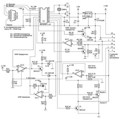
Fig.1. Wiring diagram the controller of interface of the personal computer with onboard system of self-diagnostics OBD II under reports of standards SAE (PWM and VPW) and ISO 9141-2 Mercedes-Benz W203 .

Recommendations about application
For connection diagram devices on Mercedes-Benz W203 the cable, length no more than 1.2 m that has special value at use of report PWM can be used not-screened. At use of a cable more lengths it is necessary to reduce resistance of resistors on a device input (R8 and R9 or R15). At use screened cable, the screen should be disconnected for the purpose of capacity drop.
The cable for connection to a serial port of the computer of Mercedes-Benz W203 also can be not-screened . The device stably works with a cable in length to 9 m. At much more length of a cable it is necessary to use more powerful communicator RS 232.
The topology of electric joints according to wiring diagram is any. At the raised moistness apply additional shunting condensers.
The free software (browser) for reading of codes and data for Mercedes-Benz W203 can be downloaded from sites of manufacture and is intended for use under DOS. The insignificant size of a program application in a variant «under DOS» allows to contain it on loading diskette DOS and to use even on the computers equipped incompatible with DOS with the software. An unessential condition is even presence in the hard disk computer.
READ MORE - Wiring Diagram represents the controller of interface of the personal computer Mercedes-Benz W203

2001 HONDA CIVIC WIRING DIAGRAM


Honda Civic Wiring Diagram


Table content of 2001 Honda Civic Wiring Diagram
  • Identifying Wiring Diagrams Sysmbols 2001 Honda Civic
  • Power Distribution Circuit 2001 Honda Civic
  • Ground Distribution Circuit 2001 Honda Civic
  • Anti-theft Circuit 2001 Honda Civic
  • Body Computer Circuit 2001 Honda Civic
  • Computer Data Lines 2001 Honda Civic
  • Wiring Diagram (Civic Except GX & HX 1.7L
READ MORE - 2001 HONDA CIVIC WIRING DIAGRAM
READ MORE -

Car Wiring Diagram: How to Install a Car Amp.


car wiring diagramCar Wiring Diagram warns: please do not attempt a car amp installation if you are not comfortable with the process. Leave it to a professional. Now here are the steps on how to install a car amp. There is also a wiring diagram below. These directions assume you have already physically mounted your amplifier to a solid, non-conductive surface (non-metal). If you have not purchased your power wiring be sure to read this article on choosing wire gauge for amplifiers.Attentively study our management and car wiring diagramme. 1. Determine what side of the vehicle the battery is on. Disconnect the negative battery terminal. If you have a radio with a security feature (such as a Delco-Loc or Eclipse ESN) make sure you know the reactivation code before disconnecting the negative battery terminal...
READ MORE - Car Wiring Diagram: How to Install a Car Amp.

Car Wiring Diagram:Clarion APA1100 Car Audio Amplifier wiring diagram.


car wiring diagramCar Wiring Diagram represents Clarion APA1100 Car Audio Amplifier. The Clarion APA1100 Car Audio Amplifier uses a regulated MOSFET power supply for superior control of output wattage, regardless of input voltage or musical energy content. MOSFET are chosen for their inherent characteristics to provide superior accuracy, stability and control. A toroid-coil transform yields maximum power transfer with minimum heat loss.Wiring diagram all connection and controls are on end panels and are straightforward and easy to understand. This device uses gold-plated RCA and barrier connectors to ensure best electrical connection for the amplifier system. Included is and external automotive-type fuse that is easy to replace. The following manual contains detail schematic and wiring diagram for The Clarion APA1100 Car Audio Amplifier System including single and dual mono subwoofer wiring diagram.
READ MORE - Car Wiring Diagram:Clarion APA1100 Car Audio Amplifier wiring diagram.

FORD TRACTORS WIRING HARNESSES


This is a Ford cloth wrap 9N14401-A harness. There is one wire missing where it connects from the amp gage to the starter button. This was used on 9N tractors with serial number 1 - 4000 equipped with the "A" generator and regulator and the 20-20 two post amp gage.

This is a replacement by Ford, 1960's version of the 9N 14401-B harness. It is made up of plastic wires and molded on connectors. Not like the early harness which used cloth wrap wiring. This was used on 9n tractors after serial number 4000 to 12500, equipped with the "A" generator and "loop" style amp gage.

This is a Ford, cloth wrapped 9N 14401-C. It was used on 9N tractors equipped with the "B" generator, cutout, and "loop" style amp gage from serial number 12500 up to about 35000 or so. It could also be used with the 9N10000-C generators if the tractor needed to be retrofitted with a replacement generator. Both the "B" and "C" generators were 3 brush type. The 9N 14401-D harness was the same as the "C" with one exception. The dash light wiring was not made into the harness but was a separate item.

This is a Dennis Carpenter reproduction of the original cloth wrapped 8N 14401-B main wiring harness which is used on 8Ns with a front mounted distributor up to serial number 263844. This is a Dennis Carpenter reproduction of the 8N14401-C main wiring harness. This is a rubber tape wrapped harness used on 8ns with the angle drive distributor after serial number 263843. This a Dennis Carpenter reproduction of the FAF14401-B main wiring harness. This is a rubber tape wrapped harness and was used on the 1953-54 NAA tractors.
READ MORE - FORD TRACTORS WIRING HARNESSES

AUDI A6 ELECTRICAL WIRING MANUAL


The Audi A6 Electrical Wiring Manual: 1998-2000 covers Audi A6 models built on the "C5" platform through model year 2000. This manual has been prepared using factory wiring diagrams, electrical component location information and scan tool diagnostics. Whether you’re a professional service technician or a do-it-yourself Audi owner this manual will be indispensable as a source of the same detailed electrical system information available at an authorized Audi dealer. Unfortunately Audi factory wiring diagrams are no longer available on paper.

Even an Audi owner who has no intention of working on his or her car will find that reviewing and owning this manual will make it possible to discuss repairs more intelligently with a professional service technician.

Features:
  • Coverage of USA and Canadian specification vehicles: A6 Sedan, including quattro 1998-2000 A6 Avant, including quattro 1999-2000 allroad quattro 2000
  • Wiring diagram index listing by model year and system.
  • Detailed instructions for reading wiring diagrams, identification of symbols and repair of wiring harnesses.
  • Full page wiring diagrams for standard and optional electrical equipment and systems.
  • Component location table and applicable component location illustrations.
  • Readiness code setting procedures for engine management systems.
  • Diagnostic Trouble Code (DTC) identification for OBD II mandated powertrain systems with corresponding factory DTC.
  • Control module coding tables for powertrain, body and information systems.
  • This paper wiring manual is a great supplement to the factory electronic repair information available on CD-ROM/DVD.
READ MORE - AUDI A6 ELECTRICAL WIRING MANUAL

Car Wiring Diagram :Check and ignition resetting on Subaru Legacy Outback (4-cylinder models) series В12 2001-2002.


Car Wiring Diagram it is presented car wiring diagram systems of the direct ignition, used on 4-cylinder models Subaru Legacy Outback.Before than to pass to consideration of an order of resetting of ignition we will study work of ignition system Subaru Legacy Outback according to car wiring diagram.
For the purpose of air-fuel mixture ignition in cylinders of the engine the system generates high-voltage (HV) pressure and gives out it on screwed in each of cylinders of the engine of a spark plug. Pressure should be high enough to provide "breakdown" of an air spacing between candle electrodes. Besides, "breakdown" should occur during strictly certain moment of time corresponding to current position of the bucket in the cylinder and answering to inquiries of the engine in a wide range of operational parametres.
car wiring diagram
Fig.1.Car wiring diagram ignition systems Subaru Legacy Outback (4-cylinder models).
1 - the Battery
2 - the ignition Switch
3 - the Gauge of position of a cam shaft (GCS)
4 - the Ignition coil
5 - the Spark plug
6 - the ignition Module
7 - the detonation Gauge
8 - the Front oxygen gauge
9 - the Temperature detector of a cooling fluid of the engine (TDC)
10 - the Rear oxygen gauge
11 - the Gauge of measurement of weight of air

On 4-cylinder models of an ignition coil (on one on pair cylinders) are united with the ignition module in uniform assembly as it is shown on car wiring diagram Subaru Legacy Outback.
In system DIS 4-cylinder models Subaru Legacy Outback at ignition distribution the single spark is used. At the command of ECP spark formation occurs in simultan eously two cylinders, the bucket of one of which is in the end of a timing period of compression, another - in the end of a final timing period. Thus the basic power failure is necessary on a candle of the cylinder which is in a timing period of compression in view of much more of a high pressure in it. Capacity spark formation in the second cylinder will be minimum (a single spark), providing thus reburning of molecules of an air-fuel mixture remaining in a combustion chamber that allows to achieve more effective drop of toxicity of the fulfilled gases. Spark formation occurs at a time in cylinders 1/2 and 3/4.
READ MORE - Car Wiring Diagram :Check and ignition resetting on Subaru Legacy Outback (4-cylinder models) series В12 2001-2002.
 
Copyright Car Wiring Diagrams All Rights Reserved
Powered by Home Recordings
ProSense theme created by Dosh Dosh and The Wrong Advices.
Blogerized by ExTemplates.com Blogger Templates.