Car wiring diagram: block safety locks Mazda 323 1985-1989.


car wiring diagramArrangement of safety locks

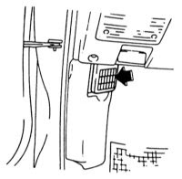
The arrangement of safety locks can differ depending on model. The arrangement of safety locks is reflected in a fuse block cover, and also in the car wiring diagram in maintenance manual. The basic safety locks of model Mazda 323 1985-1989 settle down in a box in an impellent compartment, before the left housing of an amortisation rack.


car wiring diagram


Fig. 1.Car wiring diagram arrangements of safety locks Mazda 323.


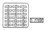
Appointment of safety locks
1-Electric window regulator
2 -stoplights, sound signal
3- steering of the engine
4 -motor of the compressor (resetting of height of a road gleam) *
5-devices
6 -antifrost screen
7 -rear marker light
8 -radio receiver, lightы resetting of mirrors
9 -rear antifog flashlights
10 -washer of headlights
11 -central stop the device
12 -internal illumination
13 -air conditioner
14 -block distributing box*
15- hatch
16 -system of a window wiper and the window washer
17 -motor of the fan
18 -rear window wiper
19 -fan of a heater
* - only on cars with an all wheel drive
car wiring diagram


Fig. 2.Car wiring diagram appointment of safety locks Mazda 323.


Nominal force of a current of a safety lock costs from an underside on the handle.It is possible to find also onwiring diagram.Besides the handle has a colour designation on which also it is possible to define nominal force of a current.
10 A - red
15 A- dark blue
20 A - yellow
30 A- light green
READ MORE - Car wiring diagram: block safety locks Mazda 323 1985-1989.

Car wiring diagram and the basic failures of starter Ford Escort 1980-1990.


car wiring diagramThe basic failures and methods of their elimination
1. At inclusion of starter the starter electric motor does not work
1.1. Failure of starter either the traction relay or defect in wires To check up being verified on car wiring diagram pressure presence on the plug 50 traction relays:
- Absence of pressure at starter inclusion testifies to damage wiring diagram an electric circuit
- Pressure presence testifies to failure of the traction relay or a starter
- If at inclusion of a starter pressure moves on the traction relay, but it does not work (there is no characteristic click), means, the traction relay (breakage of a winding or its short circuit on weight) is faulty
- Presence of characteristic click operation the traction relay testifies about scorching relay contacts or to failure of the starter
1.2. The electric motor is faulty
To check up work of the electric motor of a starter as short-term giving of pressure (an additional jump lead) on contact piece of the traction relay from the electric motor, being verified on wiring diagram. If the electric motor starts to work, means, it is necessary to search for a cause of defect in the traction relay


car wiring diagram


Fig.1. Ford Escort car wring diagram: Ford Escort starter Bosch. 1 - head; 2 - drive gear knot; 3 - drive gear lever; 4 - electromagnetic switch; 5 - stator; 6 - rotor; 7 - brush-holder


car wiring diagram


Fig.2. Car wiring diagram: Ford Escort starter Lucas. 1 - head; 2 - drive gear knot; 3 - drive gear lever; 4 - electromagnetic switch; 5 - stator; 6 - rotor; 7 - blank-end cover with a brush-holder


carwiring diagram


Fig.3.Car w iring diagram: Ford Escort starter Nippondenso 1 - head; 2 - drive gear knot; 3 - drive gear lever; 4 - electromagnetic switch; 5 - stator; 6 - rotor; 7 - brush-holder


2. The starter rotates slowly and does not start the engine
2.1. The accumulator is discharged
- To charge the accumulator
2.2. In an engine lubricating system too dense oil is filled in
- To replace oil
2.3. Graphite brushes are insufficiently pressed to a collector of the electric motor of a starter
- To adjust distance between graphite brushes and a collector
2.4. A bad condition of a work face of a collector starter bearings also are worn out
- To check up and, if necessary, to replace worn-out parts

3. At releasing the ignition key from position "starting engine operation" the starter continues to work
3.1. Sticking contact pieces of the traction relay
3.2. The ignition lock does not disconnect a starting circuit
- Immediately to switch off ignition and to disconnect the accumulator, then to eliminate failure.
READ MORE - Car wiring diagram and the basic failures of starter Ford Escort 1980-1990.

Car wiring diagram for ECM Pin-out and Connectors 1990 Pontiac Grand Prix 3.1L.


car wiring diagramIn 1990, the base model was dropped in favor of a sedan version (replacing the 6000 which ended production the next year and the Canada-only Tempest), entering production on September 12, 1989. A notable introduction for the Grand Prix in 1990 is the new STE (Special Touring Edition) which replaced the STE model of the Pontiac 6000. In contrast to that model, it trades in all-wheel-drive for the available Turbo 3.1L V6. Standard features include a cassette stereo with equilizer and eight speakers (a compact disc player was optional), remote keyless entry, eight-way power driver's seat with multiple lumbar and sidewing adjustments for both front seat occupants, and a compass/trip computer that was more informative than the units in the SE and turbo coupes. An LE sedan was also available for 1990, standard with a 2.3L Quad 4 engine and a 3-speed automatic, the first use of an inline 4 cylinder engine in a Grand Prix .


car wiring diagram


Fig.1.Car wiring diagram for ECM Pin-out and Connectors 1990 Pontiac Grand Prix 3.1L.


Car Wiring Diagram shows an wiring diagram and electric schematic on 1990 Pontiac Grand Prix 3.1L the engine steering module (ECM), a pin and connectors. 1990 Pontiac Grand Prix 3.1L the engine steering module is defined to steer an engine control system what regulates air/fuel mixture and uses a catalytic converter to minimise quantity of the pollution made from the engine. ECM (look wiring diagram) also supervises the input and exit signals, made by various gauges in systems which engages a vehicle speed sensor, the gauge of level of a cooling fluid, a various temperature detector of air, the pressure control device of air of measures, a coolant temperature detector, the oxygen gauge, the relay of the control over the fan, etc.
READ MORE - Car wiring diagram for ECM Pin-out and Connectors 1990 Pontiac Grand Prix 3.1L.
 
Copyright Car Wiring Diagrams All Rights Reserved
Powered by Home Recordings
ProSense theme created by Dosh Dosh and The Wrong Advices.
Blogerized by ExTemplates.com Blogger Templates.